
This little project started due to a friend having an office in his farm and each time he had to do work in this room during winter it was cold the first hours as he had to turn on a small radiator when he arrives.
Then came the idea to use some automation to control the heating system of the office from his smartphone!
This simple solution consists in using a Sonoff Basic R2 relay that can easily be integrated in any domotic solution.
The goal is to check the temperature of the room, set the system ON or OFF, set a temperature set point and also get the status of the heater.
For this tutorial, I will be using Jeedom… Let’s go!
1. Prerequisites
- The Sonoff Basic R2 needs to be flashed with the EspEasy firmware, there are several tutorials on the Internet so I won’t show this part.
- You need to have some experience in soldering and having basic tools to realize this tutorial.
2. Hardware list
- 1x Sonoff Basic R2 (about 10$)
- 1x Temperature Sensor DS18B20 (about 1$)
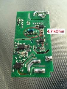
- 1x Resistor 4,7 k Ohm
- 1x Pin Headers (4 pins)
3. Assembling the components
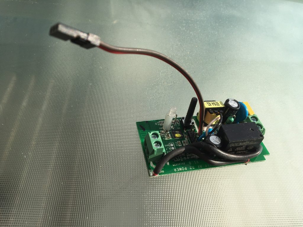
- Get the Pin Headers soldered on the Sonoff Basic R2, you can’t do any mistake as there are only 4 holes on the Sonoff Basic R2 board …

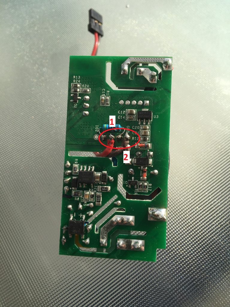
- Solder the 4,7 kOhm Resistor at the back of the sonnof board, in between VCC Pin and TX Pin.
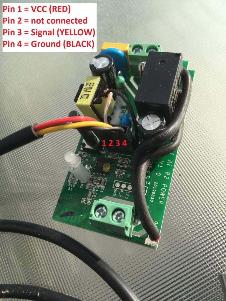
- This shows how the Temperature Sensor DS18B20 has to be connected to the PINs of the Sonoff board.
- Solder some wire on RX PIN and GROUND PIN, they will be used to switch the system on and off using a physical button.
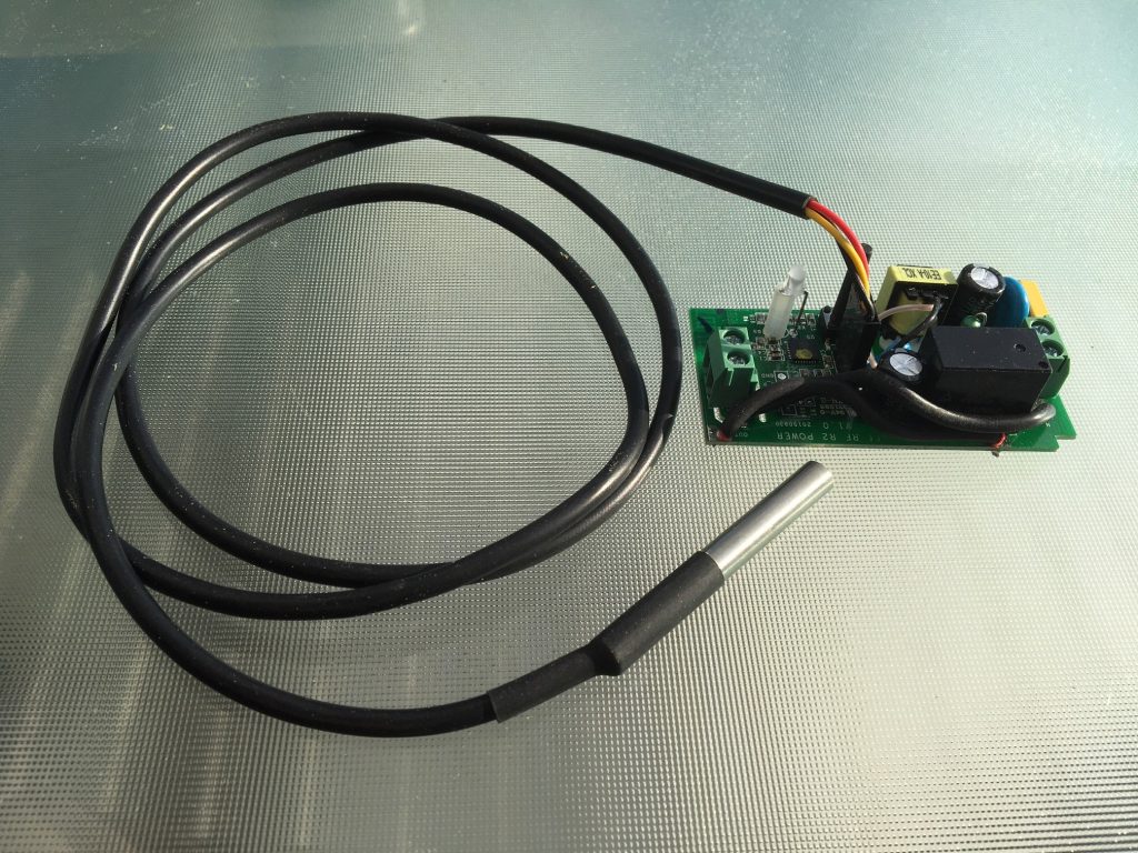
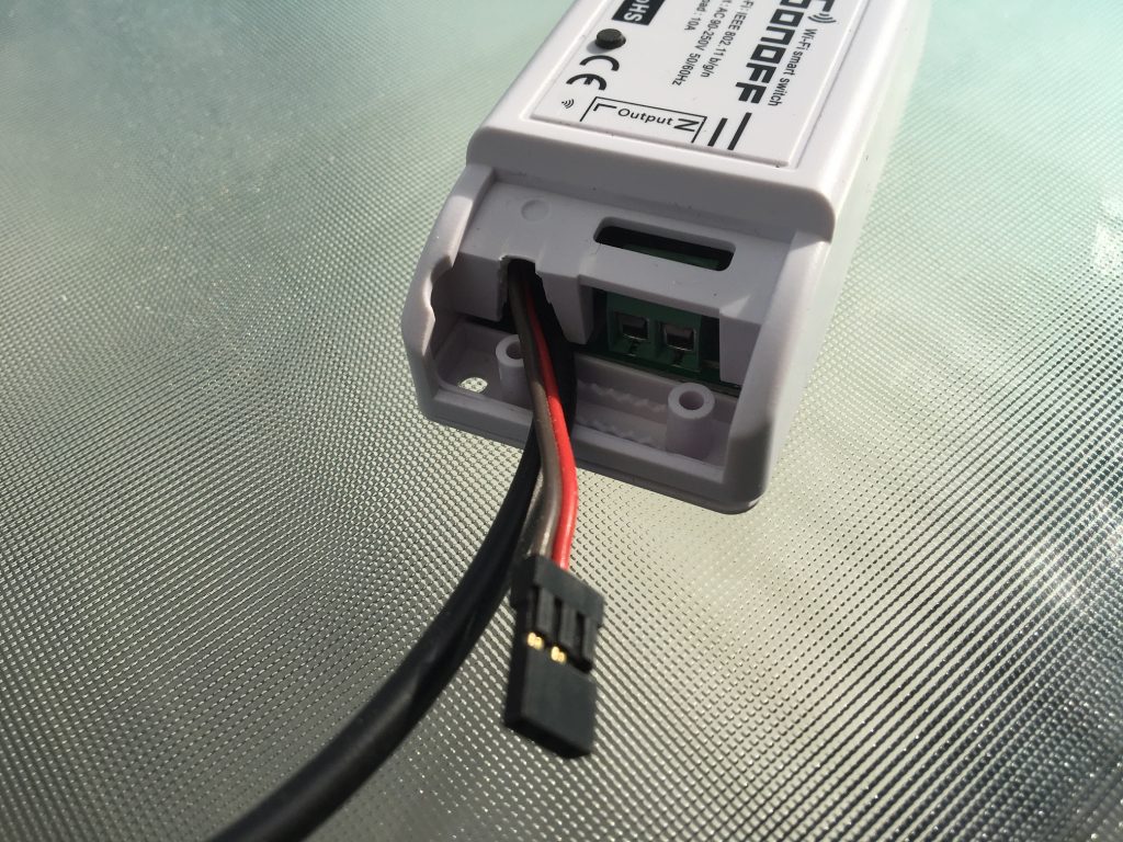
- Prepare the case so that the Temperature Sensor and the Switch Wires can find some place to get out.


- The result, once the case is closed, should look like this.
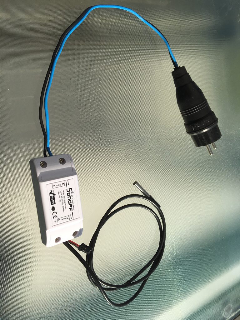
At this point the hardware part is mostly completed.
I connected a power cord at the INPUT socket and let the OUPUT socket free for now…
The OUTPUT of the Sonoff Basic R2 can directly used to connect a small device that doesn’t consume too much energy, I would recommend not to connect anything that would request more than 1000W even if the Sonoff Basic R2 allows to provide more. Instead I suggest to use a contactor / relay that will be switched on / off by the the Sonoff Basic R2 and this contactor / relay should then be adapted to the devices connected to it.
4. Setup the sotware part on the Sonoff Basic R2
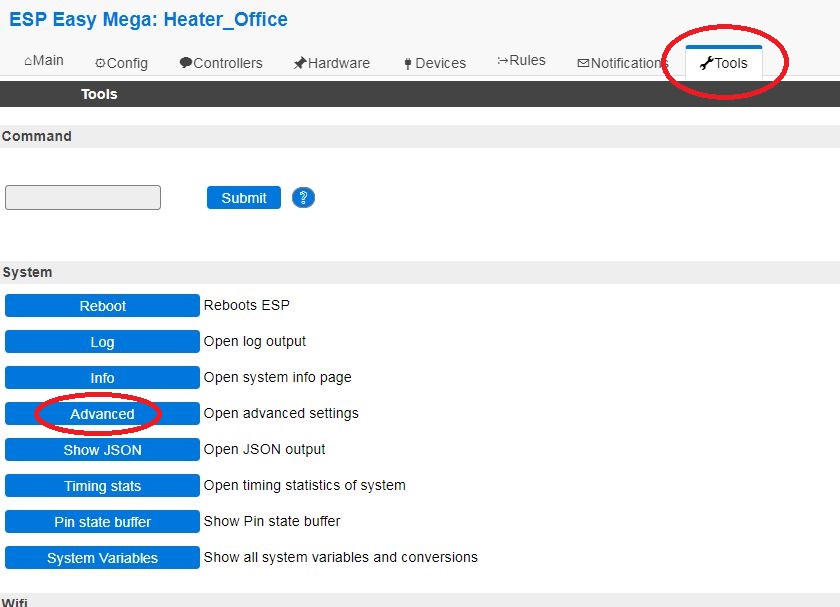
- Log into the Sonoff Basic R2 administration web page and go to Tools.
- From the Tools page, click on the Advanced button.
- In the Advanced Settings, enable the Rules option.
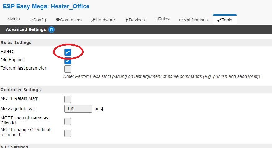
- On that same page scroll down and find the Serial Settings and uncheck the Enable Serial Port option.
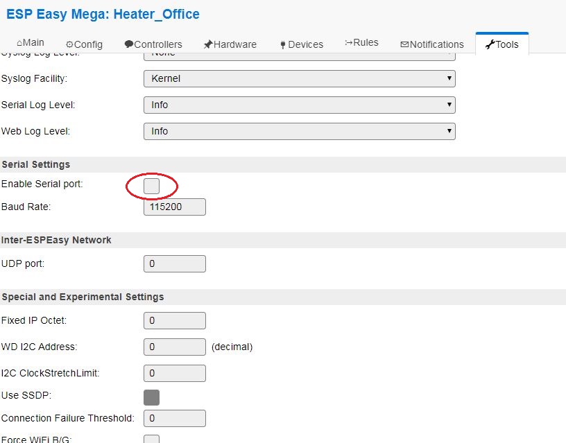
IMPORTANT : Don’t forget to click on the SUBMIT button at the bottom of the page to save the settings.
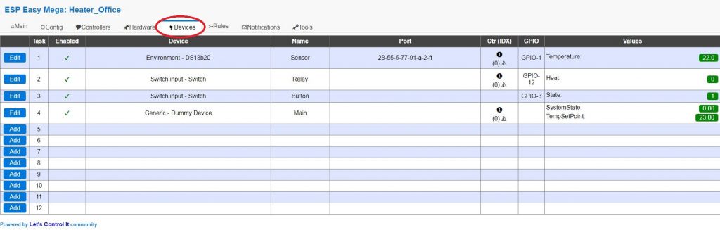
- Go to the Devices tab.
There we will setup 4 Tasks as illustrated in below picture. (details just after …)
- Definition of Task 1 :
This is the Temperature Sensor DS18B20, it is defined as the following:
Select Enviroment – DS18B20 in the list of device type when creating the Task.
Name = Sensor
Enabled = checked
GPIO = GPIO-1
Device Address = Select the once that appears in the drop box.
Device Resolution = 9
Error State Value = NaN
Send to Controller = Checked (This will send the temperature to the Domotic system)
IDX = 0
Interval = 60 seconds
Values / Name = Temperature, 1 Decimal

IMPORTANT : Don’t forget to click on the SUBMIT button at the bottom of the page to save the settings.
- Definition of Task 2 :
This is the Relay that will turn the on/off the radiator/contactor/relay, it is defined as the following:
Select Switch input – Switch in the list of device type when creating the Task.
Name = Relay
Enabled = Checked
Internal Pullup = Checked
Inversed Logic = Unchecked
GPIO = GPIO-12
Switch Type = Switch
Switch Button Type = Normal Switch
Send Boot State = Unchecked
De-Bounce = 0
Doubleclick Event = Disabled
Longpress Event = Disabled
Use Safe Button = Unchecked
Send to Controller = Checked (This will be used to get the status of the heater (heating / not in function)
IDX = 0
Interval = 0
Values / Name = Heat
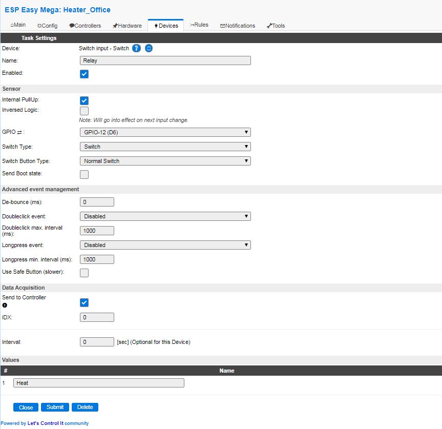
IMPORTANT : Don’t forget to click on the SUBMIT button at the bottom of the page to save the settings.
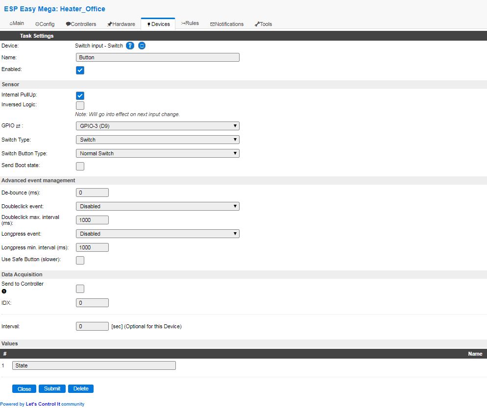
- Definition of Task 3 :
This is the Button (physical) that will be used turn the system on/off, it is defined as the following:
Select Switch input – Switch in the list of device type when creating the Task.
Name = Button
Enabled = Checked
Internal Pullup = Checked
Inversed Logic = Unchecked
GPIO = GPIO-3
Switch Type = Switch
Switch Button Type = Normal Switch
Send Boot State = Unchecked
De-Bounce = 0
Doubleclick Event = Disabled
Longpress Event = Disabled
Use Safe Button = Unchecked
Send to Controller = Unchecked (We don’t need to send this information to the controller, what we will be interrested in is the feedback that will be defined in the Task 4.)
Values / Name = State
IMPORTANT : Don’t forget to click on the SUBMIT button at the bottom of the page to save the settings.
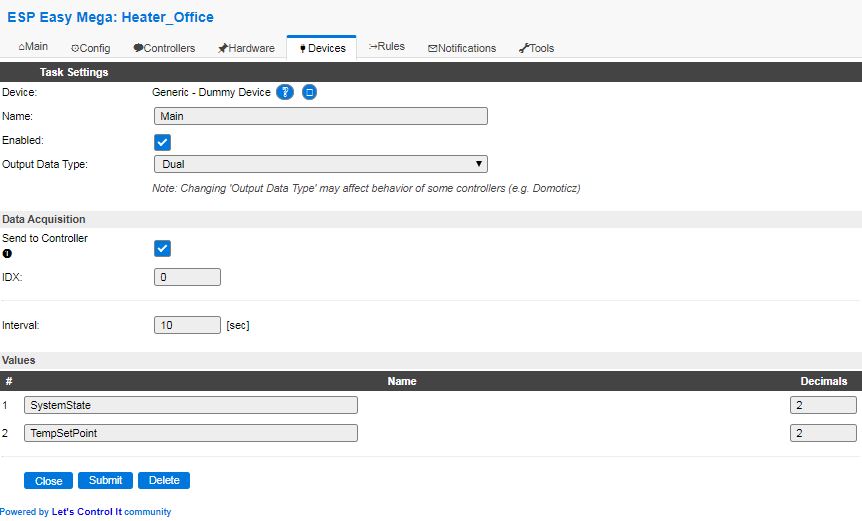
- Definition of Task 4 :
This is the Main task that will be used to hold the system state (is it on or off) and also to store the temperature set point, it is defined as the following:
Select Generic – Dummy Device in the list of device type when creating the Task.
Name = Main
Enabled = Checked
Output Data Type = Dual
Send to Controller = Checked
IDX = 0
Interval = 10 seconds
Values / Name (1) = SystemState, 2 decimals
Values / Name (2) = TempSetPoint, 2 decimals
IMPORTANT : Don’t forget to click on the SUBMIT button at the bottom of the page to save the settings.
All devices are now set up!
- Go to the Rules tab to define the Rules Set 1 :
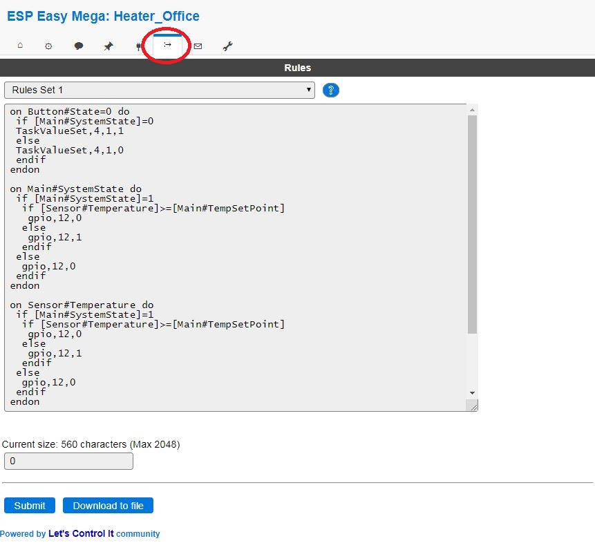
Copy the code from the below code area and paste it into the Rules Set 1 of the Sonoff Basic R2.
IMPORTANT : Don’t forget to click on the SUBMIT button at the bottom of the page to save the settings.
on Button#State=0 do
 if [Main#SystemState]=0
 TaskValueSet,4,1,1
 else
 TaskValueSet,4,1,0
 endif
endon

on Main#SystemState do
 if [Main#SystemState]=1
  if [Sensor#Temperature]>=[Main#TempSetPoint]
   gpio,12,0
  else
   gpio,12,1
  endif
 else
  gpio,12,0
 endif
endon

on Sensor#Temperature do
 if [Main#SystemState]=1
  if [Sensor#Temperature]>=[Main#TempSetPoint]
   gpio,12,0
  else
   gpio,12,1
  endif
 else
  gpio,12,0
 endif
endon

on Relay#Heat do
 if [Relay#Heat]=0
  gpio,13,1
 else
  gpio,13,0
 endif
endon
5. Setup the Domotic system
I’m using Jeedom (I’m french and really like this system, Jeedom’s team is fantastic!) so this is just for your information.
You would need to adapt to your Domotic system.
The EspEasy plugin from Lunarok has to be installed on Jeedom to get this working.
Reference: https://lunarok.github.io/jeedom_docs/plugins/espeasy/
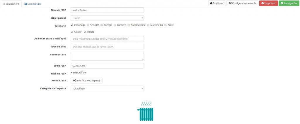
- Setup a new ESP equipment into Jeedom :
During the Sonoff Basic R2 inclusion all Information Commands will be automatically created.
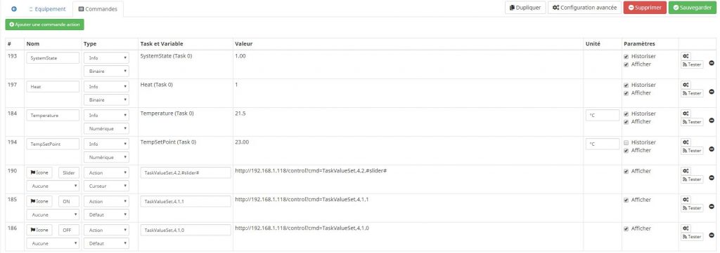
- Define the Action Commands as following :
Command 1
Name = Slider
Type = Action/Curseur
Task = TaskValueSet,4,2,#slider# (This will send the temperature set point to the Sonoff Basic R2)
Command 2
Name = ON
Type = Action/Defaut
Task = TaskValueSet,4,1,1 (This will set the System State to 1 (ON))
Command 3
Name = OFF
Type = Action/Defaut
Task = TaskValueSet,4,1,0 (This will set the System State to 0 (OFF))
The result on the dashboard is looking nice 🙂
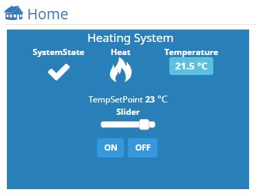
END