
This project is to control a swimming pool equipments: watter pump, PH dosing, ORP and pool lights.
It is as well designed to automate the regulation based on the water temperature, current PH and ORP.
The system is able to also take give some setpoint and interfacing with any home automation system via simple HTTP protocol.
The solution consists in using a Sonoff Basic 4CH Pro relay that can easily be integrated in any domotic solution.
All the logic will be programmed into internal rules.
For this tutorial, I will be using Jeedom… Let’s go!
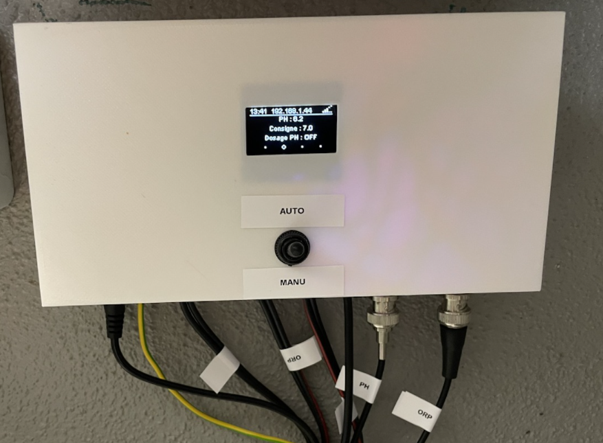
The end result should be to produce a device like this:
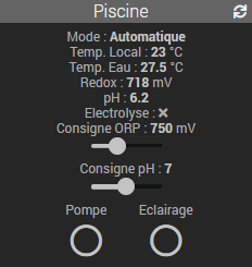
Interfaced with your domotic system, in my case Jeedom:
1. Prerequisites
- The Sonoff Basic 4CH Pro needs to be flashed with the EspEasy firmware, there are several tutorials on the Internet so I won’t show this part.
- You need to have some experience in soldering and having basic tools to realize this tutorial.
2. Hardware list
- 1x Sonoff Basic 4CH Pro (about 10$)
- 1x Temperature Sensor DS18B20 (about 1$)
- 1x Resistor 4,7 k Ohm
- 1x OLED SSD1306 Display (about 5$)
- 2x pH/ORP 1130 (about 35$ each)
- 1x ADS1115 I2C Interface (about 5$)
- 1x BMP280 Sensor (about 5$)
- 1x PH Sensor (about 20$)
- 1x ORP Sensor (about 20 $)
- 1x Pin Headers
- Some wiring/cables
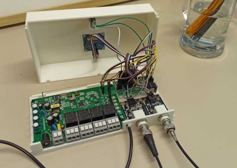
3. Assembly diagram
Let’s see how to get all these parts together!
Find below the case in in STL format, you can the use your 3D printer to get your own case !
The case:
The cover:
X. Setup the software part on the Sonoff Basic 4CH Pro
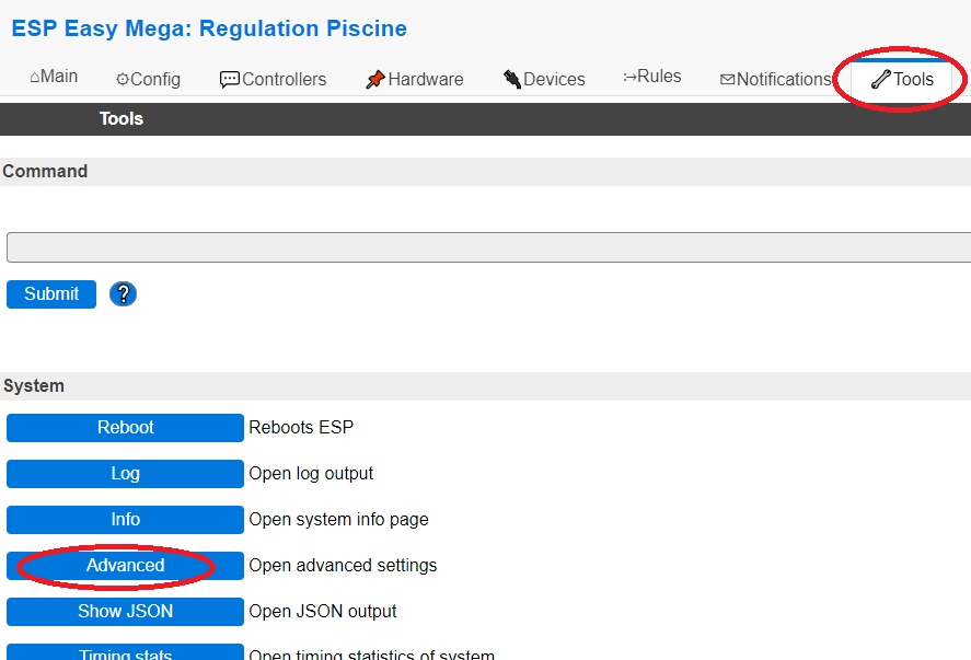
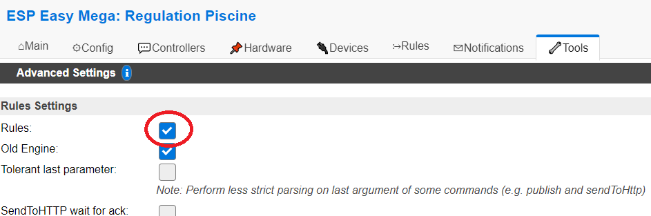
- Log into the Sonoff Basic 4CH Pro administration web page and go to Tools.
- From the Tools page, click on the Advanced button.
- In the Advanced Settings, enable the Rules option.
- On that same page scroll down and find the Serial Settings and uncheck the Enable Serial Port option.
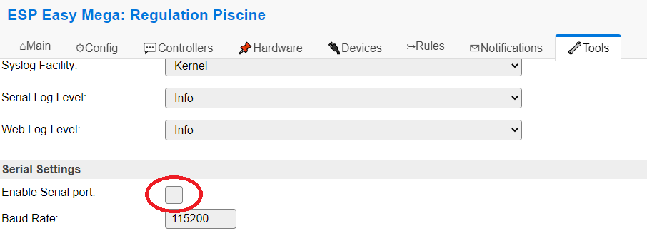
IMPORTANT : Don’t forget to click on the SUBMIT button at the bottom of the page to save the settings.
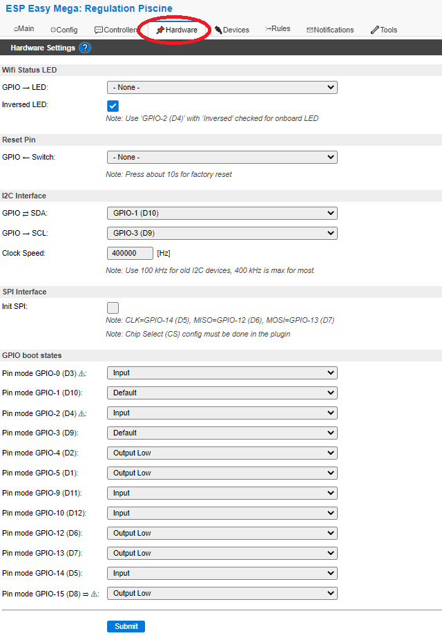
- Go to the Hardware tab and set as below:
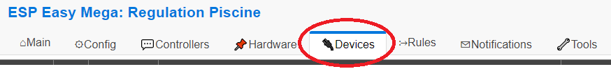
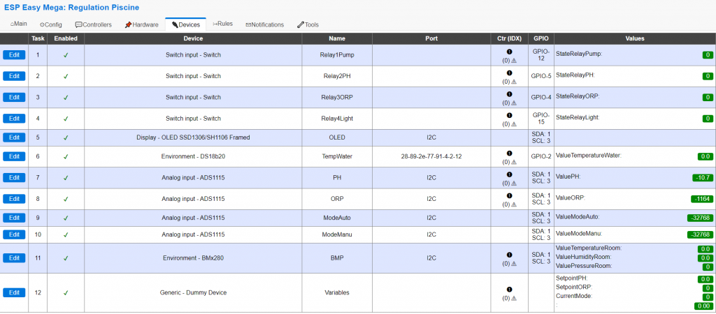
- Go to the Devices tab :
There we will setup 12 Tasks as illustrated in below picture. (details just after …)
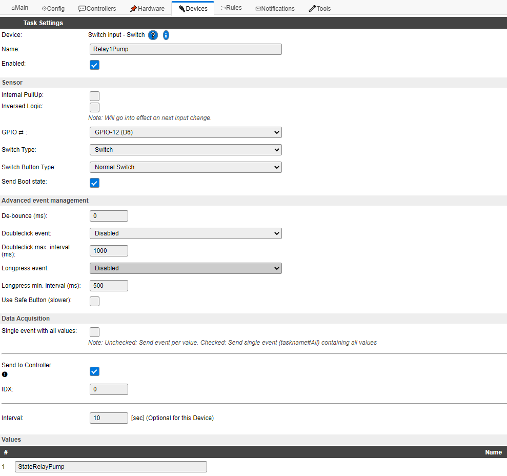
- Definition of Task 1 :
This is the Relay 1 that will turn the water pump on/off, it is defined as the following:
Select Switch input – Switch in the list of device type when creating the Task.
Name = Relay1Pump
Enabled = Checked
Internal Pullup = Unchecked
Inversed Logic = Unchecked
GPIO = GPIO-12
Switch Type = Switch
Switch Button Type = Normal Switch
Send Boot State = Checked
De-Bounce = 0
Doubleclick Event = Disabled
Longpress Event = Disabled
Use Safe Button = Unchecked
Send to Controller = Checked (This will be used to get the status of the heater (heating / not in function)
IDX = 0
Interval = 10 [sec]
Values / Name = StateRelayPump
IMPORTANT : Don’t forget to click on the SUBMIT button at the bottom of the page to save the settings.
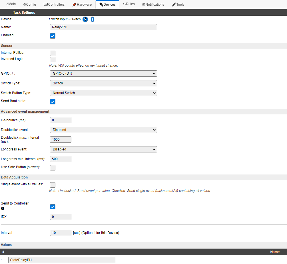
- Definition of Task 2 :
This is the Relay 2 that will turn the PH regulation pump on/off, it is defined as the following:
Select Switch input – Switch in the list of device type when creating the Task.
Name = Relay2PH
Enabled = Checked
Internal Pullup = Unchecked
Inversed Logic = Unchecked
GPIO = GPIO-12
Switch Type = Switch
Switch Button Type = Normal Switch
Send Boot State = Checked
De-Bounce = 0
Doubleclick Event = Disabled
Longpress Event = Disabled
Use Safe Button = Unchecked
Send to Controller = Checked (This will be used to get the status of the heater (heating / not in function)
IDX = 0
Interval = 10 [sec]
Values / Name = StateRelayPH
IMPORTANT : Don’t forget to click on the SUBMIT button at the bottom of the page to save the settings.
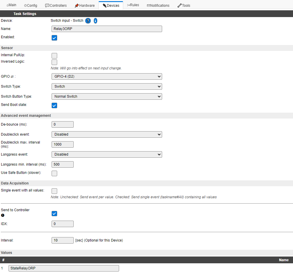
- Definition of Task 3 :
This is the Relay 3 that will turn the ORP regulation (Electrolyzer) on/off, it is defined as the following:
Select Switch input – Switch in the list of device type when creating the Task.
Name = Relay3ORP
Enabled = Checked
Internal Pullup = Unchecked
Inversed Logic = Unchecked
GPIO = GPIO-12
Switch Type = Switch
Switch Button Type = Normal Switch
Send Boot State = Checked
De-Bounce = 0
Doubleclick Event = Disabled
Longpress Event = Disabled
Use Safe Button = Unchecked
Send to Controller = Checked (This will be used to get the status of the heater (heating / not in function)
IDX = 0
Interval = 10 [sec]
Values / Name = StateRelayORP
IMPORTANT : Don’t forget to click on the SUBMIT button at the bottom of the page to save the settings.
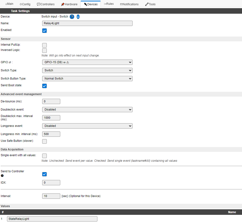
- Definition of Task 4 :
This is the Relay 4 that will turn the swimming pool lights on/off, it is defined as the following:
Select Switch input – Switch in the list of device type when creating the Task.
Name = Relay4Light
Enabled = Checked
Internal Pullup = Unchecked
Inversed Logic = Unchecked
GPIO = GPIO-12
Switch Type = Switch
Switch Button Type = Normal Switch
Send Boot State = Checked
De-Bounce = 0
Doubleclick Event = Disabled
Longpress Event = Disabled
Use Safe Button = Unchecked
Send to Controller = Checked (This will be used to get the status of the heater (heating / not in function)
IDX = 0
Interval = 10 [sec]
Values / Name = StateRelayLight
IMPORTANT : Don’t forget to click on the SUBMIT button at the bottom of the page to save the settings.
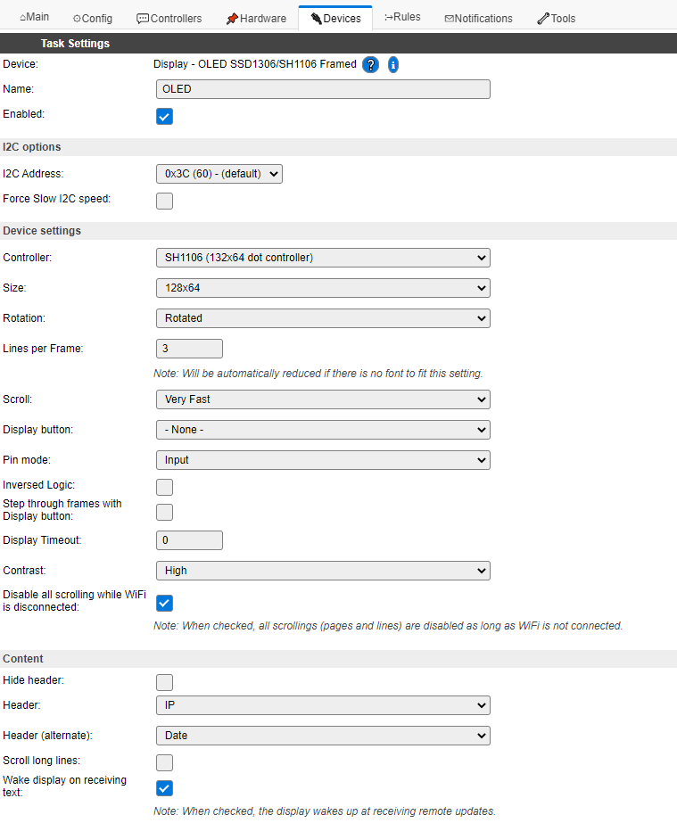
- Definition of Task 5 :
This is the OLED Display that will show all information on the regulation device, it is defined as the following:
Select Display – OLED SSD1306/SH1106 Framed in the list of device type when creating the Task.
Name = OLED
Enabled = Checked
Controller = SSD1306 (128×64 dot controller)
I2C Address = 0x3C (60) – (default)
Size = 128×64
Rotation = Rotated
Lines per Frame = 3
Scroll = Very Fast
Display button = None
Inversed Logic = Unchecked
Display Timeout = 0
Contrast = High
Header = IP
Header (alternating) = Date
Scroll long lines = Unchecked
Wake display on receiving text = Checked
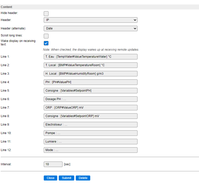
Line 1 = T. Eau : [TempWater#ValueTemperatureWater] °C
Line 2 = T. Local : [BMP#ValueTemperatureRoom] °C
Line 3 = H. Local : [BMP#ValueHumidityRoom] g/m3
Line 4 = PH : [PH#ValuePH]
Line 5 = Consigne : [Variables#SetpointPH]
Line 6 = Dosage PH : …
Line 7 = ORP : [ORP#ValueORP] mV
Line 8 = Consigne : [Variables#SetpointORP]
Line 9 = Electroliseur : …
Line 10 = Pompe : …
Line 11 = Lumiere : …
Line 12 = Mode : …
Interval = 10 [sec]
IMPORTANT : Don’t forget to click on the SUBMIT button at the bottom of the page to save the settings.
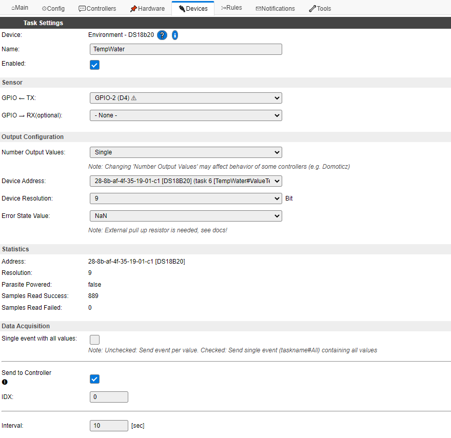
- Definition of Task 6 :
This is the Temperature Sensor DS18B20 to measure the swimming pool water temperature, it is defined as the following:
Select Enviroment – DS18B20 in the list of device type when creating the Task.
Name = TempWater
Enabled = checked
GPIO = GPIO-2
Device Address = Select the once that appears in the drop box.
Device Resolution = 9
Error State Value = NaN
Send to Controller = Checked (This will send the temperature to the Domotic system)
IDX = 0
Interval = 10 [sec]
Values / Name = ValueTemperatureWater, 1 Decimal

IMPORTANT : Don’t forget to click on the SUBMIT button at the bottom of the page to save the settings.
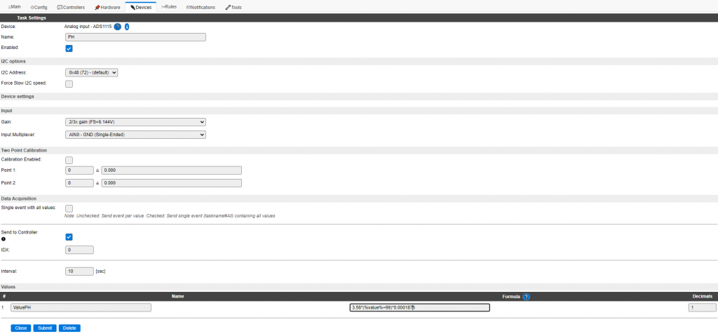
- Definition of Task 7 :
This is the ADS1115 Interface to measure the swimming pool water PH value, it is defined as the following:
Select Analog input – ADS1115 in the list of device type when creating the Task.
Name = PH
Enabled = Checked
I2C Address = 0x48 (72) – (default)
Gain = 2/3x gain (FS=6.144V)
Input Multiplexer = AIN0 – GND (Single-Ended)
Calibration Enabled = Unchecked
Point 1 = 0 ≙ 0.000
Point 2 = 0 ≙ 0.000
Send to Controller = Checked
IDX = 0
Interval = 10 [sec]
Values / Name = Name = ValuePH , Formula = 3.56 * (%value%+99) * 0.0001875 , Decimals = 1
About the Formula “3.56 * (%value%+99) * 0.0001875″ … you can adjust the ph sensor by adding or substracting a value in the formula like:
3.56 * (%value%+99) * 0.0001875 + x, where x to adjust the ph sensor
IMPORTANT : Don’t forget to click on the SUBMIT button at the bottom of the page to save the settings.
- Definition of Task 8 :
This is the ADS1115 Interface to measure the swimming pool water ORP value, it is defined as the following:
Select Analog input – ADS1115 in the list of device type when creating the Task.
Name = ORP
Enabled = Checked
I2C Address = 0x48 (72) – (default)
Gain = 2/3x gain (FS=6.144V)
Input Multiplexer = AIN0 – GND (Single-Ended)
Calibration Enabled = Unchecked
Point 1 = 0 ≙ 0.000
Point 2 = 0 ≙ 0.000
Send to Controller = Checked
IDX = 0
Interval = 10 [sec]
Values / Name = Name = ValueORP , Formula = (2.5-(%value%+99)*0.0001875)/0.001037 , Decimals = 0
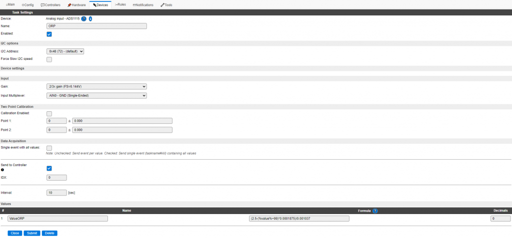
IMPORTANT : Don’t forget to click on the SUBMIT button at the bottom of the page to save the settings.
- Definition of Task 9 :
This is the ADS1115 Interface to set the swimming pool ModeAuto value, it is defined as the following:
Select Analog input – ADS1115 in the list of device type when creating the Task.
Name = ModeAuto
Enabled = Checked
I2C Address = 0x48 (72) – (default)
Gain = 16x gain (FS=0.256V)
Input Multiplexer = AIN2 – GND (Single-Ended)
Calibration Enabled = Unchecked
Point 1 = 0 ≙ 0.000
Point 2 = 0 ≙ 0.000
Send to Controller = Checked
IDX = 0
Interval = 2 [sec]
Values / Name = Name = ValueModeAuto , Decimals = 0
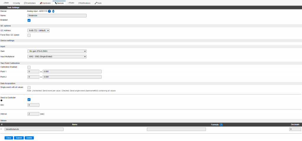
IMPORTANT : Don’t forget to click on the SUBMIT button at the bottom of the page to save the settings.
- Definition of Task 10 :
This is the ADS1115 Interface to set the swimming pool ModeManu value, it is defined as the following:
Select Analog input – ADS1115 in the list of device type when creating the Task.
Name = ModeManu
Enabled = Checked
I2C Address = 0x48 (72) – (default)
Gain = 16x gain (FS=0.256V)
Input Multiplexer = AIN3 – GND (Single-Ended)
Calibration Enabled = Unchecked
Point 1 = 0 ≙ 0.000
Point 2 = 0 ≙ 0.000
Send to Controller = Checked
IDX = 0
Interval = 2 [sec]
Values / Name = Name = ValueModeManu , Decimals = 0

IMPORTANT : Don’t forget to click on the SUBMIT button at the bottom of the page to save the settings.
- Definition of Task 11 :
This is the BMP820 Sensor to get the technical room humidity, pressure and temperature values, it is defined as the following:
Select Environment – BMx280 in the list of device type when creating the Task.
Name = BMP
Enabled = Checked
I2C Address = 0x76 (118) – (default)
Altitude = 130 [m]
Temperature offset = 0 [x 0.1C]
Send to Controller = Checked
IDX = 0
Interval = 10 [sec]
Values
1 Name = ValueTemperatureRoom , Decimals = 1
2 Name = ValueHumidityRoom , Decimals = 1
3 Name = ValuePressureRoom , Decimals = 0
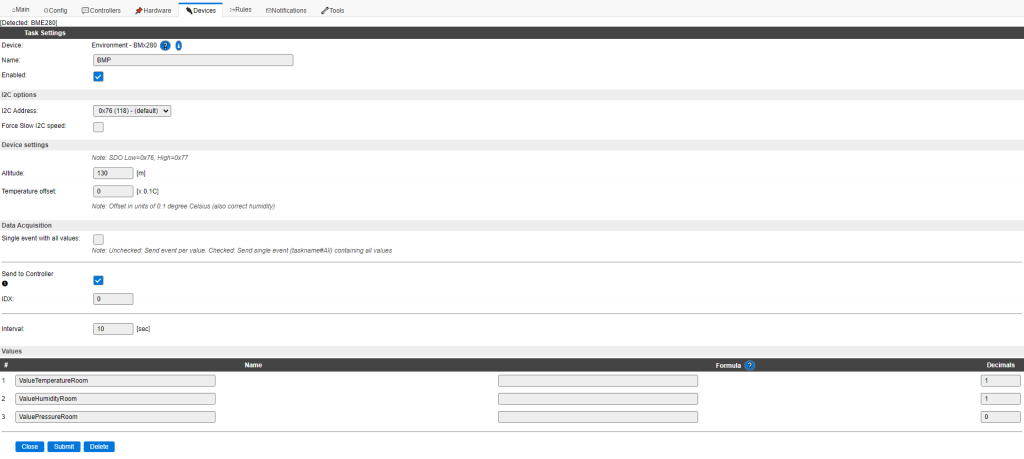
IMPORTANT : Don’t forget to click on the SUBMIT button at the bottom of the page to save the settings.
- Definition of Task 12 :
This task is to define some varibles needed to store some values (setpointsm mode), it is defined as the following:
Select Generic – Dummy Device in the list of device type when creating the Task.
Name = Variables
Enabled = Checked
Output Data Type = Triple
Send to Controller = Checked
IDX = 0
Interval = 10 [sec]
Values
1 Name = SetpointPH , Decimals = 1
2 Name = SetpointORP , Decimals = 0
3 Name = CurrentMode , Decimals = 0
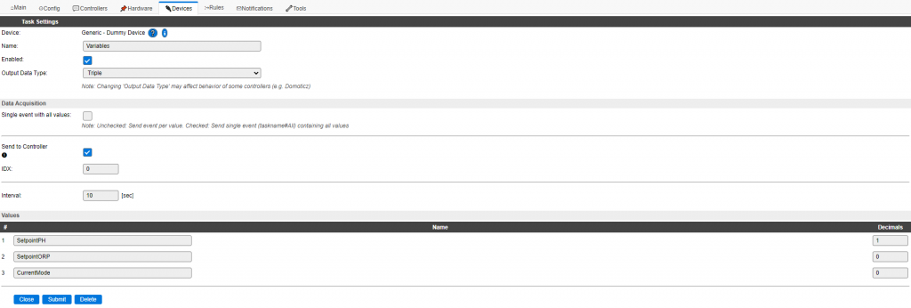
IMPORTANT : Don’t forget to click on the SUBMIT button at the bottom of the page to save the settings.
All devices are now set up!
- Go to the Rules tab to define the Rules Set 1 :
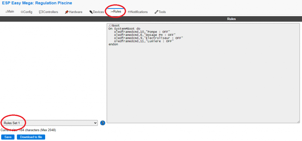
Copy the code from the below code area and paste it into the Rules Set 1 of the Sonoff Basic 4CH Pro.
//Boot
On System#Boot do
   oledframedcmd,10,"Pompe : OFF"
   oledframedcmd,6,"Dosage PH : OFF"
   oledframedcmd,9,"Electroliseur : OFF"
   oledframedcmd,11,"Lumiere : OFF"
endon
IMPORTANT : Don’t forget to click on the SUBMIT button at the bottom of the page to save the settings.
- Go to the Rules tab to define the Rules Set 2 :
Copy the code from the below code area and paste it into the Rules Set 2 of the Sonoff Basic 4CH Pro.
//PH
On Variables#SetpointPH do
   if [Relay1Pump#StateRelayPump]=1 and [Relay2PH#StateRelayPH]=0 and [PH#ValuePH]>[Variables#SetpointPH] and [TempWater#ValueTemperatureWater]>15
      GPIO,5,1
   endif
   if [Relay1Pump#StateRelayPump]=1 and [Relay2PH#StateRelayPH]=1 and [PH#ValuePH]<=[Variables#SetpointPH]
      GPIO,5,0
   endif
   if [TempWater#ValueTemperatureWater]<16
      GPIO,5,0
   endif
endon

//ORP
On Variables#SetpointORP do
   if [Relay1Pump#StateRelayPump]=1 and [Relay3ORP#StateRelayORP]=0 and [ORP#ValueORP]<[Variables#SetpointORP] and [TempWater#ValueTemperatureWater]>15
      GPIO,4,1
   endif
   if [Relay1Pump#StateRelayPump]=1 and [Relay3ORP#StateRelayORP]=1 and [ORP#ValueORP]>=[Variables#SetpointORP]
      GPIO,4,0
   endif
   if [TempWater#ValueTemperatureWater]<16
      GPIO,4,0
   endif
endon
IMPORTANT : Don’t forget to click on the SUBMIT button at the bottom of the page to save the settings.
Copy the code from the below code area and paste it into the Rules Set 3 of the Sonoff Basic 4CH Pro.
- Go to the Rules tab to define the Rules Set 3 :
//Pump
On Relay1Pump#StateRelayPump do
   if [Relay1Pump#StateRelayPump]=1 and [Relay2PH#StateRelayPH]=0 and [PH#ValuePH]>[Variables#SetpointPH] and [TempWater#ValueTemperatureWater]>15
      GPIO,5,1
   endif
   if [Relay1Pump#StateRelayPump]=1 and [Relay3ORP#StateRelayORP]=0 and [ORP#ValueORP]<[Variables#SetpointORP] and [TempWater#ValueTemperatureWater]>15
      GPIO,4,1
   endif
   if [Relay1Pump#StateRelayPump]=1
      oledframedcmd,10,"Pompe : ON"
   else
      GPIO,5,0
      GPIO,4,0
      oledframedcmd,10,"Pompe : OFF"
   endif
endon

//PH
On Relay2PH#StateRelayPH do
   if [Relay1Pump#StateRelayPump]=1 and [Relay2PH#StateRelayPH]=0 and [PH#ValuePH]>[Variables#SetpointPH] and [TempWater#ValueTemperatureWater]>15
      GPIO,5,1
   endif
   if [Relay1Pump#StateRelayPump]=1 and [Relay2PH#StateRelayPH]=1 and [PH#ValuePH]<=[Variables#SetpointPH] and [TempWater#ValueTemperatureWater]>15
      GPIO,5,0
   endif
   if [Relay2PH#StateRelayPH]=0
      oledframedcmd,6,"Dosage PH : OFF"
   else
      oledframedcmd,6,"Dosage PH : ON"
   endif
endon

//ORP
On Relay3ORP#StateRelayORP do
   if [Relay1Pump#StateRelayPump]=1 and [Relay3ORP#StateRelayORP]=0 and [ORP#ValueORP]<[Variables#SetpointORP] and [TempWater#ValueTemperatureWater]>15
      GPIO,4,1
   endif
   if [Relay1Pump#StateRelayPump]=1 and [Relay3ORP#StateRelayORP]=1 and [ORP#ValueORP]>=[Variables#SetpointORP] and [TempWater#ValueTemperatureWater]>15
      GPIO,4,0
   endif
   if [Relay3ORP#StateRelayORP]=0
      oledframedcmd,9,"Electroliseur : OFF"
   else
      oledframedcmd,9,"Electroliseur : ON"
   endif
endon

//Light
On Relay4Light#StateRelayLight do
   if [Relay4Light#StateRelayLight]=1
      oledframedcmd,11,"Lumiere : ON"
   else
      oledframedcmd,11,"Lumiere : OFF"
   endif
endon
IMPORTANT : Don’t forget to click on the SUBMIT button at the bottom of the page to save the settings.
- Go to the Rules tab to define the Rules Set 4
//Modes
On ModeAuto#ValueModeAuto do
   if [ModeAuto#ValueModeAuto]=32752 and [ModeManu#ValueModeManu]!=32752 and [VAR#1]!=2
      let,1,2
      TaskValueSet,12,3,2
      gpio,12,0
      gpio,4,0
      gpio,5,0
      oledframedcmd,12,"Mode : Auto"
   endif
   if [ModeAuto#ValueModeAuto]<32752 and [ModeManu#ValueModeManu]<32752 and [VAR#1]!=0
      let,1,0
      TaskValueSet,12,3,0
      gpio,12,0
      gpio,4,0
      gpio,5,0
      oledframedcmd,12,"Mode : Arrêt"
   endif
endon
On ModeManu#ValueModeManu do
   if [ModeManu#ValueModeManu]=32752 and [ModeAuto#ValueModeAuto]!=32752 and [VAR#1]!=1
      let,1,1
      TaskValueSet,12,3,1
      gpio,4,0
      gpio,5,0
      gpio,12,1
      oledframedcmd,12,"Mode : Forcé"
   endif
   if [ModeAuto#ValueModeAuto]<32752 and [ModeManu#ValueModeManu]<32752 and [VAR#1]!=0
      let,1,0
      TaskValueSet,12,3,0
      gpio,12,0
      gpio,4,0
      gpio,5,0
      oledframedcmd,12,"Mode : Arrêt"
   endif
endon
IMPORTANT : Don’t forget to click on the SUBMIT button at the bottom of the page to save the settings.